As a project manager, engineer or field technician one of the most important parts of your job is selecting the equipment that you’ll be responsible for throughout its service life. Control valves are vital to how a system functions, and if not sized and selected appropriately, can be major pain points. Sizing a control valve is something most understand to be a necessary and vital part of any project. The dirty little secret that most are unaware of: selecting the correct controller for a valve can be the key to a long lasting, low maintenance system. The following information will help you avoid the valve that just won’t calibrate, a maintenance cycle that seems to never end and the sense line labyrinth that annoys even the most experienced technicians.
Easy Solutions to Common Problems
Have you ever had a control valve that turns into a problem child during or shortly after installation and startup? Maybe multiple engineers have reviewed and confirmed the correct sizing, specifications, application guidelines, and on paper the valve assembly seems to check every box. However, we have all been exposed to unexpected setpoint drift, loss of travel range, unmanageable oscillations and shortened service life. How could this happen? The answer may lie in how much time was invested in selecting the correct positioner or controller.
Controllers and Positioners, What Are They?
Having an experienced salesperson in your back pocket will always be the best way to get a detailed evaluation and explanation for your specific application. However, familiarity with a few key concepts will help you understand what is being requested and offered. Here we are going to focus on the theory behind Controllers and Positioners, including a few examples.
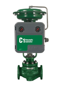
The function of a Pneumatic controller is to listen to an input (line pressure) and to tell the control valve how to adjust with an output (A proportional pneumatic signal) without direct verification (stem position feedback) that the valve is doing what it is told. There is indirect verification (resulting line pressure) however this method is less accurate then direct stem position feedback. The C1 diagram in Example 1 below is an example of this type of controller. For most dump valve and pressure reducing applications that don’t require precise actuation as well as applications in remote areas without a Remote Terminal Unit (RTU), this will be your starting point. It is important to note that without additional accessories, troubleshooting and maintaining this product will be a hands on process. If there are changes to system requirements (large set point adjustments, bench set requirements etc.) pressure controllers may require physical components to be removed and installed.
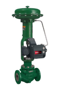
Pneumatic Positioners force a valve to a specific position proportional to an air signal which has a pre-determined pneumatic range (0-30 psi for example). A mechanical linkage is typically used to communicate how much travel has actually occurred resulting from an air signal to the actuator.
If the valve does not respond as expected due to issues with the valve internals or unexpected packing friction, it will boost or reduce the signal to the actuator until it arrives at the appropriate position. The pre-determined pneumatic signal will typically come from a level controller or pneumatic controller (discussed in more detail below).
Detailed Walkthrough of Valve Positioners: https://www.youtube.com/watch?v=dNq4H9WfrfE
If there is no RTU available and stability is dependent on tuning accuracy, then pneumatic controllers can be installed in conjunction with pneumatic positioners. Tubing and troubleshooting can be more complex, but these options are typically forced by the lack of an RTU or control system and accuracy requirements.
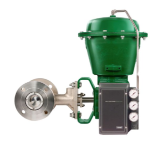
The industry standard for Electro Pneumatic Positioners is the fisher DVC6200. If your system is controlled electronically, the DVC6200 should be your first choice. DVC’s use magnetic arrays mounted against the stem or cam of a valve to verify that the valve is reacting correctly to the pneumatic signal sent from the DVC to the actuator and that this has resulted in the desired valve travel. More simply put, a DVC adjusts the 4-20 mA input to a proportional signal (like a controller) and verifies travel (like a positioner).

")
")
")